|
|
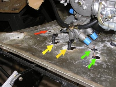
Red Arrow: This is the stud for GROUND wires.
Yellow Arrows: These are the pre-welded guides for the IGNITION COILS.
Green Arrows: These are the studs for the REGULATOR.
|
|
|
|
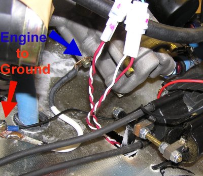
Red Arrow: The GROUND Stud
Blue Arrow: The Engine connected to the Ground Stud using the
large white cable.
|
|
|
|
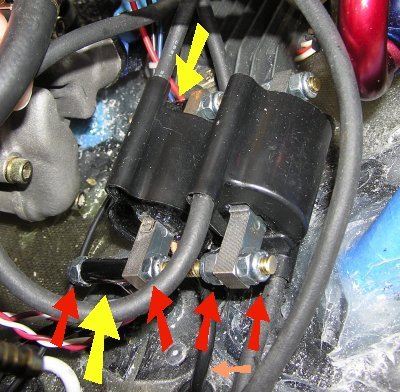
Yellow Arrows: Pre-Welded Guides for the Ignition Coils
Red Arrows: Nylock nuts mounted on a long brass threaded rod
(Ed designed this and Mark concurred).
The HKS does not have space to install the ignition coils on either side of the guides,
as you could with the Rotax 503. So we put BOTH
ignition coils on ONE SIDE of the guide.
(Orange Arrow: There are 2 orange cables that will attach to
the ignition control modules under the engine pan - all this
will be covered in the upcoming "wiring" section.)
|
|
|
|
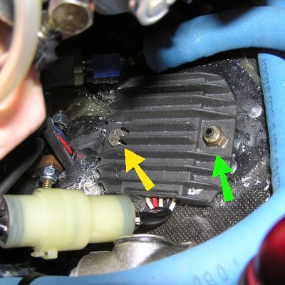
Green Arrow: One Regulator Stud. The HKS Engine gets in
the way of the second stud. Per Mark, we cut off the
second stud. Then we drilled a hole
in the engine pan and bolted the second side of the
regulator.
Yellow Arrow: Our new bolt into the engine pan.
|
|
|
|
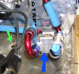
Blue Arrow: The Oil Thermostat will sit in front of the Regulator
(Green arrow shows Regulator Stud).
Do not drill the oil thermostat down until you put the oil hoses on. The
position will change slightly based on the hose lengths.
(See "Oil System" section)
|
|
|
|
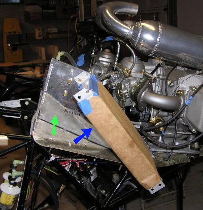
Blue Arrow: Oil Cooler. We covered this with brown paper
to keep it clean and safe while we worked.
Green Arrow: Oil Cooler Mount. This gets riveted to the
engine pan and bolted to the rear of the wing 'middle box'.
It is best to position this with the wing in place.
Notice in Mark's photos that there is space between the
oil cooler and the 'side' of the wing 'middle box'. That leaves
room for the flap control horn.
|
|
|
|
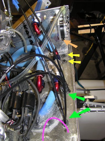
Yellow Arrows: You will need to drill and rubber grommet
2 holes in the engine pan for
Fuel Hoses. One is for fuel input into the Pneumatic Fuel
Pump (ORANGE Arrow). The other is for fuel output from the
Electric Fuel Pump (under the engine pan) into the carburetors.
(See upcoming Fuel System page for full details).
Green Arrows: You will need to drill & rubber grommet 2 holes for cables.
One will be for the Throttle Cables and one will be for the Choke
Cables.
Pink Line: You will also need to drill & rubber grommet
1 hole in the engine pan for the oil sump tank vent tube.
We have not drilled this hole yet and are not yet sure where
we will postition this tube. The Pink Line is just a simulation.
|
|
|
|
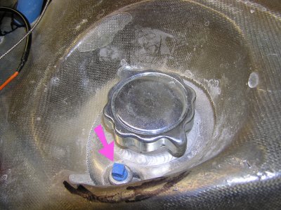
Pink Arrow: Oil Sump Vent opening. The vent tube needs to
go up 4 inches then down through the engine pan to the
bottom of the plane.
|
|