Home Page ----- Odyssey Home Page ----- Previous Page ----- Next Page
Engine Area - Where Things Go (1 of 3)

Where things go in the engine area (1 of 3)

UNDER the Engine Pan

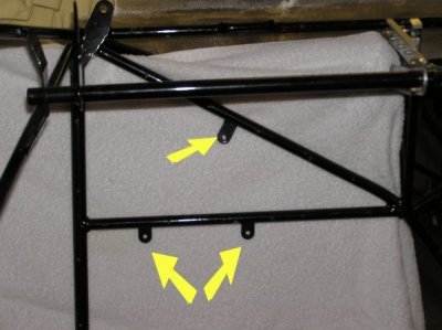
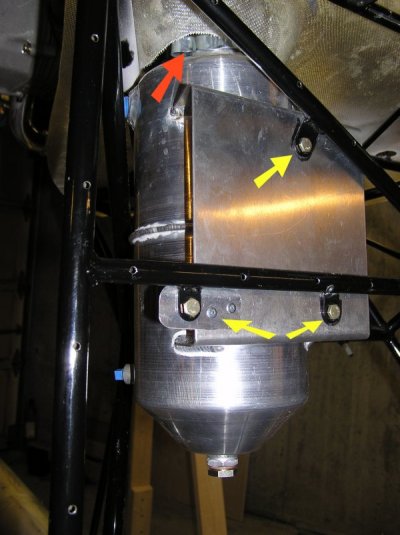
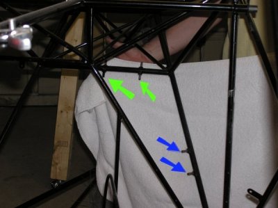
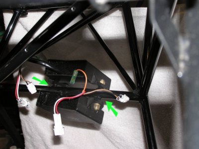
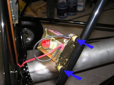
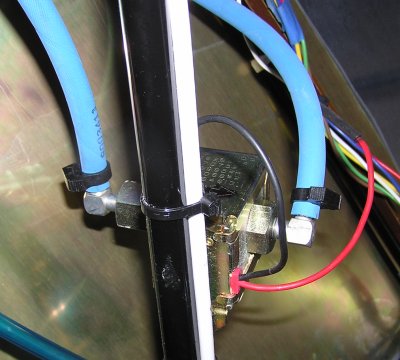
Mounting the Oil Sump Tank, Ignition Control Modules & Electric Fuel Pump

(These three pages only show where/how to mount engine components. See upcoming sections on the Oil System, Fuel System and Wiring for full assemblies.)


The Oil Sump Tank gets mounted on the 3 tabs behind the student seat.

Oil Sump Tank mounted.

Red Arrow: The top of the Sump Tank is above the engine pan.

Yellow Arrows: The tank did not fit well on the 3 tabs. We riveted an aluminum extension onto the Sump Tank plate (lower left). Because the bolt is so close to the original tab and because the plate is so thick, the installation is very secure.

(The routing of the oil hoses is described later.)

Green Arrows - the Ignition Control Modules go on the upper studs behind the pilot. One Module sits above the tube and one sits below it.

Blue Arrows - the Electric Fuel Pump goes on the lower studs behind the pilot.

Green Arrows - the Ignition Control Modules.

(The electrical connections will be described in the wiring section).

Blue Arrows - the Electric Fuel Pump.

Look carefully on the pump. You will find arrows showing the direction of fuel flow - in and out.

This photo shows the 'out' (red cap) pointing toward the front of the plane. We reversed this when we added the fuel line.

Final assembly of the electric fuel pump. The input is toward the front of the plane (left) and the output is toward the rear (right).

We needed to purchase brass barb fittings that replace the red caps (Mark told us what size we needed - I cannot remember). We also used plastic 90 degree barb fittings (capable of handling fuel - Lockwood Aviation). This keeps the fuel lines straight and relaxed.

(The electrical connections will be described in the wiring section).

Home Page ----- Odyssey Home Page ----- Previous Page ----- Next Page