Home Page ----- Odyssey Home Page -----Previous Page ----- Next Page
Week Three

Week Three

Continuing the wing assembly.
Mounting the Aileron Torque Tube and Driver Arms

Mounting the aileron torque tube is not inherently difficult. But, you must pay close attention to what you are doing. The entire assembly must be kept in a straight line and the clearances between the tubes and the rib lightening holes must also be taken into account.

The assembly consists of two aluminum tubes (of different lengths), four driver arms and three supports.

The torque tube runs at an angle inside the 5 inch lightening holes of the ribs. The tube is near the top surface of the wing on the left side and near the bottom surface of the wing on the right side. The driver arms, on each end, point toward the center of the wing spar axis.

Ponder this in your head, or get a pencil to use as a visual aid, and roll it back and forth. You'll see how the left aileron driver arm would go up while the right went down and vice-versa.


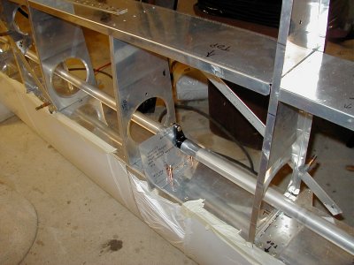
Here's a shot of the center support and the aligmnent guage provided by EarthStar (there'll be more info on the alignment gauges on the next page).

It may be difficult to tell from this angle, but if you look closely, you can see that the torque tube is going through the lightening holes at an angle.

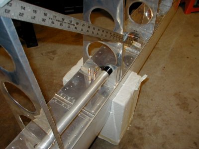
Here's the left wing aileron driver arm.

Notice how this end of the aileron torque tube is near the top surface of the wing.

The ruler in this shot is held on with a couple of cleco side clamps. It's simply acting as a temporary triangulation stiffener.

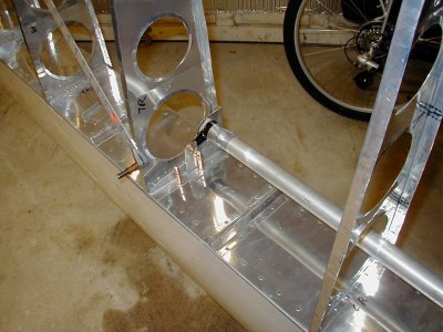
The right aileron driver arm.

Notice how this end of the torque tube is near the bottom surface of the wing.

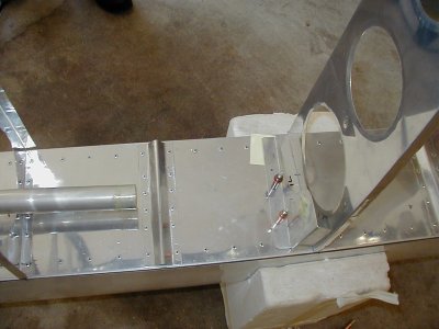
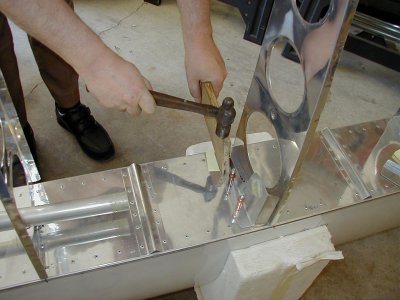
The end rivets on the torque tube supports frequently interfere with the existing spar cap rivet. So, you must remove the existing rivet and then re-use the hole.

Here's the technique we used to locate the hole location on the torque tube support.

  • Before removing the existing rivet, lay a postage stamp size PostIt note on the rivet with the sticky side up.
  • Cleco the support in, using a couple of the existing holes.
  • Give the support a gentle wrap with a board and hammer, directly over the existing rivet.
  • Voila ... An indent of the existing rivet location is left in the PostIt note which is conveniently stuck to the support. Just center punch it and drill it out.
  • You can now remove the existing rivet.


Marking the existing rivet location on the PostIt note.

I monkeyed with the contrast in this photo. But, if you look closely, you can see the indent of the existing rivet in the paper.

Home Page ----- Odyssey Home Page -----Previous Page ----- Next Page