JET Energy, Inc.
JET Energy | JET Tech | NANOR Tech | PHUSOR Tech | JET Refs | CHERRY Tech | Contact
JET Energy PHUSOR®-type Metamaterial Technology 
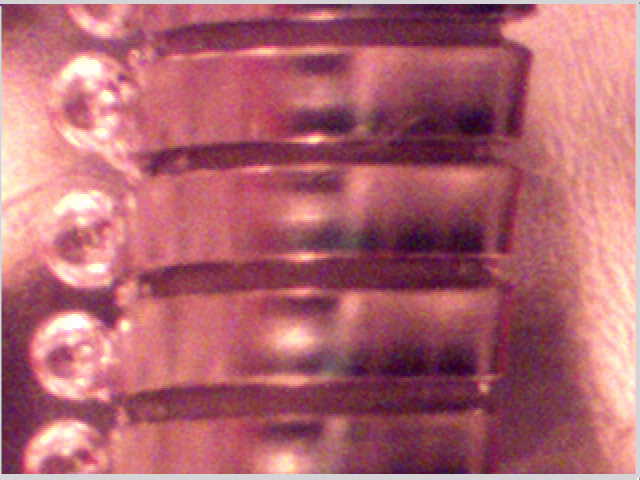
JET PHUSOR®-type Electrode Metamaterial Heating Technology - This figure demonstrates an important finding of this system - asymmetric electrolysis which is seen on only one side of the cathode (which is facing the anode). In this high voltage system (~1500 volts), videos (including those shown at ICCF-10 by Dr. Mitchell Swartz, of which the above figure is a single frame grab) have demonstrated that cathodic electrolysis bubbling occurs, if the conditions are appropriate, almost solely on the anode-side (left hand portion of the spiral wound cathode in the photo) of this PHUSOR®-type heating electrode system. As shown above, the JET PHUSOR®-type electrode system is different from others in the field. The figure also heralds the forced movement of the loaded deuterons through the loaded metal. This creates a deuteron current through the palladium electrode, and an improved likelihood of success in LANR.
JET ENERGY 2003 LANR OPEN DEMONSTRATION AT MIT 
The MIT ICCF-10 JET Energy, Inc. Lattice-Assisted Nuclear Reaction (LANR) Demonstration
Shown at ICCF-10 at MIT, Cambridge, MA, August '03], the JET Energy, Inc. Demonstration system produced excess heat over five days. Videos and other data were shown to hundreds of visitors demonstrating how this system is different from other systems. The energy gain was ~2.7 in 2003.
JET Energy, Inc. - ICCF-10 Demonstration

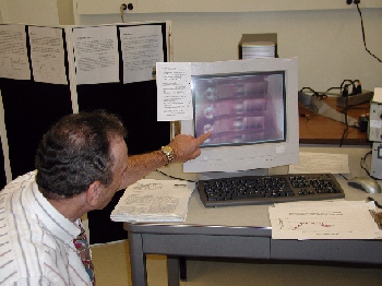
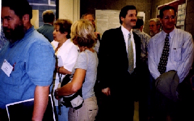

From "COLD FUSION", the "21st Century" radio show on 4/18/04, by Dr. Bob Hieronimus with guests Dr. Eugene Mallove and Dr. Mitchell Swartz.
Dr Mallove: "The existence of the cold fusion demonstrations [the JET Thermal Product ICCF10 Demonstration unit and the students from Oregon under Prof. Dash] at MIT warmed my soul because MIT is our alma mater, our mutual alma mater. Dr. Swartz and I are both MIT graduates. We are disappointed very greatly by its hot fusion people attacking cold fusion. So this conference and demonstration was sort of redemption, you might say. I mean here we had at MIT a working reactor that was within a few thousand feet of the Tokamak hot fusion laboratory which has consumed something like approximately a half billion dollars federal funds over the last 15 years. The hot fusion graduate students have learned this or that but the program is going absolutely no where. And here just a few thousand feet away in a public setting, attended mostly by people who were attending the ICCF-10 conference but including many other members of the public, there was a working cold fusion reactor.
The overall experience was positive and that fact, historically, will never be erased at this point. In the year 2003, an actual working cold fusion reactor of significant performance, and very accurately measured performance, was done by an MIT graduate, namely Dr. Swartz, at MIT."
Dr. Swartz: "The cold fusion demonstration experiment at MIT during the last International Cold Fusion Conference (ICCF-10) in August 200 involved a cold fusion device, called a "Phusor", which was operated for seven days at MIT, during the week of ICCF-10 in Cambridge. And during the week, we had a mean excess power gain, compared to the ohmic, control of 2.3. That is a 230 percent increase of observed energy released compared to the ohmic resistor control which is defined as 100 percent. The range of electrical input powers ranged from about 120 milliwatts up to 1.5 watts. Now the interesting part was that the purpose of the open-house experiment was to demonstrate the "optimal operating point" of these cold fusion reactions. The public and attendees responded and there appeared to be somewhere between 150 and 200 people on the afternoon of Tuesday who came to MIT from the ICCF-10 meeting. Drs. Mallove and Hagelstein invited all of Boston, in fact, through advertisements in the Boston Globe."
"The purpose of the MIT and ICCF-10 demonstration was both to exhibit and examine two things. First, we wanted to find out if we could make one of these devices portable. Second, the purpose of the week-long demonstration was to teach the attendees and visitors about the existence of the optimal operating point in driving these cold fusion systems. And what I mean by that is the following; the optimal operating point is the peak system operation point in the input power axis, and that region is called a "point" because it is quite narrow. Thus, one reason for the difficulty in obtaining successful cold fusion experiments is that the performance of one of these cold fusion devices usually has a discrete, narrow, region of electrical operation. It is so narrow that if you attempt to operate a cold fusion device outside of that region, its performance drops drastically. In 1989."
"I think Martin Fleischmann and Stanley Pons inadvertently and unintentionally appeared to make cold fusion appear easier to achieve than it actually is. However, cold fusion is rather difficult to obtain. Cold fusion was missed in the beginning in 1989 by many people who tried to reproduce it. Tried but failed because they did not recognize many important issues including loading, material preparation, and the optimal operating point."
"So the purpose of the demonstration at MIT was to teach the visitors and the attendees the presence of this optimal region of cold fusion device operation by demonstrating to the people assembled for ICCF-10 Cold Fusion Conference this behavior involving peak performance of a cold fusion device."
"During the demonstration, we changed the operating characteristics of this device by raising the applied voltage, in 50 volt increments, from approximately 200 volts up to 800 volts across the system. We watched the power generated, the device performance, fall. When, eventually, the demonstration's applied voltage increased to 700 to 800 volts, the device performance was even less than that of the ohmic control resistor, meaning that there was no more excess heat. The excess heat returned when the applied voltage was decreased back towards 200 volts. That demonstration of the optimal operating point was the second purpose of the demonstration. The achievability of cold fusion was the first. I think in the future we will determine whether the optimal operating point performance of the cold fusion device as taught, was learned by the visiting audience. But certainly the appearance of excess heat by cold fusion was seen by hundreds of people and was thereafter well reported."
PHUSOR® is a registered trademark of JET Energy, Incorporated. NANOR®-type technology, and PHUSOR®-type technology, and other discussed IP herein is protected by U.S. Patents D596724, D413659 and other Patents pending.
JET Energy, Inc. |
"Working on the Most Efficient and Cleanest Heat Products Available" |